README.md
1# The Arduino Compatible for STM32G474 Nucleo development board
2
3**English** | [中文](README_zh.md)
4
5## 1 RTduino - Arduino Ecosystem Compatibility Layer for RT-Thread
6
7The STM32G474 Nucleo development board has been fully adapted with the [RTduino software package](https://github.com/RTduino/RTduino), which is an Arduino Ecosystem compatibility layer for RT-Thread. Users can program this BSP according to Arduino programming conventions and use a large number of libraries available in the Arduino community, providing a significant enhancement to the RT-Thread ecosystem. For more information, please refer to the [RTduino software package documentation](https://github.com/RTduino/RTduino).
8
9### 1.1 How to Enable Arduino Ecosystem Compatibility Layer for this BSP
10
11Enter the menuconfig command under Env tool or select RT-Thread Settings under RT-Thread Studio IDE:
12
13```Kconfig
14Hardware Drivers Config --->
15 Onboard Peripheral Drivers --->
16 [*] Compatible with Arduino Ecosystem (RTduino)
17```
18
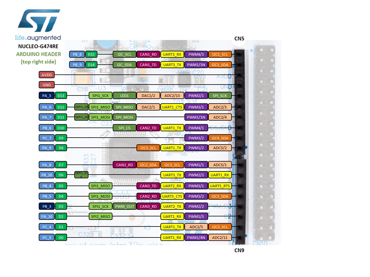
19## 2 Arduino Pinout
20
21For additional information on pin layout, refer to [pins_arduino.c](pins_arduino.c) and [pins_arduino.h](pins_arduino.h).
22
23
24
25
26
27
28| Arduino Pin Number | STM32 Pin Number | 5V Tolerance | Remarks |
29| ------------------- | --------- | ---- | ------------------------------------------------------------------------- |
30| 0 (D0) | PC5 | Yes | |
31| 1 (D1) | PC4 | Yes | |
32| 2 (D2) | PA10 | Yes | Serial2-RX, default controlled by RT-Thread's UART device framework uart1 |
33| 3 (D3) | PB3 | Yes | PWM2-CH2, default controlled by RT-Thread's PWM device framework pwm2 |
34| 4 (D4) | PB5 | Yes | |
35| 5 (D5) | PB4 | Yes | PWM3-CH1, default controlled by RT-Thread's PWM device framework pwm3 |
36| 6 (D6) | PB10 | Yes | PWM2-CH3, default controlled by RT-Thread's PWM device framework pwm2 |
37| 7 (D7) | PA8 | Yes | |
38| 8 (D8) | PA9 | Yes | Serial2-TX, default controlled by RT-Thread's UART device framework uart1 |
39| 9 (D9) | PC7 | Yes | PWM8-CH2, default controlled by RT-Thread's PWM device framework pwm8 |
40| 10 (D10) | PB6 | Yes | PWM4-CH1, default controlled by RT-Thread's PWM device framework pwm4 |
41| 11 (D11) | PA7 | Yes | PWM3-CH2, default controlled by RT-Thread's PWM device framework pwm3 |
42| 12 (D12) | PA6 | Yes | |
43| 13 (D13) | PA5 | Yes | Onboard User LED |
44| 14 (D14) | PB9 | Yes | I2C1-SDA, default controlled by RT-Thread's I2C device framework i2c1 |
45| 15 (D15) | PB8 | Yes | I2C1-SCL, default controlled by RT-Thread's I2C device framework i2c1 |
46| 16 (D16) | PC13 | Yes | |
47| 17 (A0) | PA0 | Yes | ADC1-CH1, default controlled by RT-Thread's ADC device framework adc1 |
48| 18 (A1) | PA1 | Yes | ADC1-CH2, default controlled by RT-Thread's ADC device framework adc1 |
49| 19 (A2) | PA4 | Yes | ADC2-CH17, default controlled by RT-Thread's ADC device framework adc2 |
50| 20 (A3) | PB0 | Yes | ADC1-CH15, default controlled by RT-Thread's ADC device framework adc1 |
51| 21 (A4) | PC1 | Yes | ADC1-CH7, default controlled by RT-Thread's ADC device framework adc1 |
52| 22 (A5) | PC0 | Yes | ADC1-CH6, default controlled by RT-Thread's ADC device framework adc1 |
53| 23 (A6) | -- | | On-chip reference voltage ADC, default controlled by RT-Thread's ADC device framework adc1 |
54| 24 (A7) | -- | | On-chip temperature sensor ADC, default controlled by RT-Thread's ADC device framework adc1 |
55
56> Notice:
57>
58> 1. Don't use a same hardware timer to drive PWM (analogRead) and servos at same time, because hardware timers can only generate a same frequency for 4 PWM channels. Otherwise, it could cause a failure when drive servos.
59
60> References:
61> 1. [stm32-nucleo-64-boards-mb1136-stmicroelectronics.pdf](https://www.st.com/resource/en/user_manual/dm00105823-stm32-nucleo-64-boards-mb1136-stmicroelectronics.pdf)
62> 2. [ST-Nucleo-G474RE](https://os.mbed.com/platforms/ST-Nucleo-G474RE)
63